![]()
Modern receiver technology can be implemented using a number of architectures, each with advantages and disadvantages depending on the final application. In all cases, an increasing involvement with Digital Signal Processing (DSP) is evident. The use of DSP technology can either provide ancillary enhancement to various receiver performance, or become a central processing engine in the overall receiver system.
The most common receiver architectures are,
| Tuned Radio Frequency (TRF) - Most common versions are "super regenerative" minimal component" designs suitable for garage door openers. | |
| Super-heterodyne (Superhet) frequency conversion - Most popular architecture with a single, double or triple frequency down conversion approach. | |
| Direct Conversion (DC) Analogue RF to IQ Approach- Still in its infancy but shows great promise when combined with suitable DSP enhancement algorithms. | |
| Direct RF Signal Acquisition "DRFSA - RF to ADC approach" - Relatively new architecture intended to capture and digitize complete chunks of RF spectrum and resolve individual signals completely in the digital domain, each with arbitrary modulation format demodulation capability, individual data rates and corresponding occupied bandwidths. |
TRF approaches began with the first radio receiver inventions based on
"crystal set" diode detectors or early vacuum tube (valve) devices
 . This approach was suitable for Amplitude Modulation (AM) and used
relatively few components - an extremely important issue in a time (1930's or
so) when the cost of components, especially vacuum tube devices, was relatively
high.
. This approach was suitable for Amplitude Modulation (AM) and used
relatively few components - an extremely important issue in a time (1930's or
so) when the cost of components, especially vacuum tube devices, was relatively
high.
Unfortunately these TRF architectures were unable to receive weak signals or to separate signals with close frequency spacing. In addition they had some propensity for instability especially if several RF amplifier stages were used.
These limitations resulted from the need to provide RF signal processing directly at the RF input frequency. Although feasible at relatively low RF frequencies (e.g. Medium Wave AM @ 550 kHz to 1,650 kHz), difficulties with TRF approached became insurmountable at higher "short-wave" and higher VHF and UHF frequencies. The "super-regen" or "rush-box" as it was sometimes called had been used for early VHF communications and provided an interesting technical approach to improving receiver sensitivity. A good super-regen could receive AM signals as low as a few µV (micro-volts) but still had bandwidth issues (usually required signals to be separated by a few MHz). The advent of the super-heterodyne or "superhet" receiver topology changed all this. The RF signal information was conveniently shifted to a lower, fixed frequency, where signal processing could be more easily achieved.
The use of a much lower (and fixed) Intermediate Frequency (IF) allowed the received signals to be amplified to a much greater extent than in the TRF approach, and with far less danger of instability due to the lower frequencies involved. Selectivity (i.e. the ability to discriminate between closely spaced frequencies) was also greatly improved. This was further assisted by the availability of highly selective, but fixed frequency, filter components based on quartz resonators (crystal (Xtal) filters and later Surface Acoustic Wave or "SAW" filters using different substrate materials).
Every "solution" to a problems tends to have unexpected drawbacks and the superhet is no exception. Whilst the task of RF and IF signal processing was simplified, the introduction of "spurious response" susceptibility was introduced. The most notable of these include the "image" response corresponding to equal reception potential at (FRF = FLO ± FIF ) in addition to potential reception at integer harmonics of the LO frequency (FRF = N * FLO ± FIF where N = 2, 3, 4, etc)
This spurious response susceptibility required the need for extra RF selectivity based on tunable Band Pass Filtering preceding the receive frequency down conversion mixer (s). Additional spurious response mechanisms and can be referred to as "complex" responses (the previous spurious responses are termed "linear" or "simple" spurii. Complex responses are non linear and occur at frequencies predicted from harmonic combinations of both RF and LO frequencies. In some cases these occur close to the wanted receive frequency - on exactly on the same frequency (referred to as "coherent complex spurii") and therefore cannot be eliminated by filtering.
So although the superhet offers useful solutions it does suffer from some potential weakness. The solutions required involve additional complexity and cost needed to filter unwanted simple responses or costs associated with high performance frequency down conversion mixers needed to suppress complex spurious responses. Further, several frequency conversions may also be needed, each adding additional complexity and cost.
An alternative "Analog RF to IQ" architecture has always aroused interest. This approach also seeks to place the task of signal processing at a much lower, and therefore convenient frequency. Referred to as "Direct Conversion" or DC, this approach uses an Analogue RF to I-Q demodulator component to generate an In-Phase "Channel" and Quadrature-Phase "Q Channel" output usually centered at FIQ = 0 Hz. Signal amplification, filtering, equalization, enhancements and final demodulation then occurs at the "IQ Complex Baseband" signal domain.
The IQ outputs contain relatively low spectral frequency components compared to the incoming RF frequency. They can be easily processed by relatively inexpensive ADC devices - these are often available as dual "2 ADC's in one package" components. The problem of spurious responses is alleviated to a large extent and RF filtering is only required to remove responses at harmonics of the LO frequency (simple responses) and potential sub-harmonic responses of the LO frequency caused by potential non linearity in the Analog IQ demodulator component.
The "image" response is eliminated - or more correctly used as a fundamental part of the frequency conversion process. The IQ signal can be considered as a dual channel signal with positive and negative spectral components corresponding to spectral energy above and below the LO frequency.
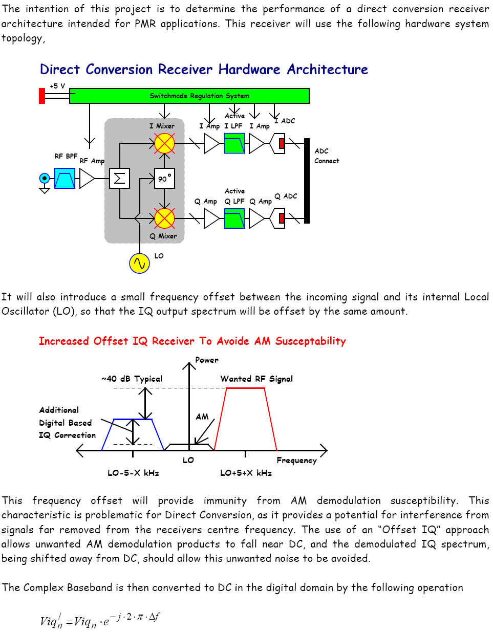
Note: An "offset IQ" approach is also possible, in which case the IQ spectrum is not centered exactly at zero Hz ± ½ · RFBW . This results in an unwanted image response but this may be manageable depending on the application's performance requirements.
As with the superhet, Direct Conversion has some technical drawbacks,
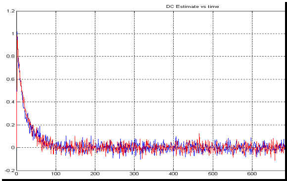
| Residual DC voltage appearing at the I and Q output channels - May be a few mV compared to signals in the region of µV - referred to as "IQ DC offset error". | |
| Slight imbalances in RF to I and RF to Q channel amplitudes - Modern Analog IQ Demodulators can have less than ±0.2 dB of IQ gain imbalance - referred to as "IQ gain imbalance error". | |
| Imperfect 90 degree phase offset between the I and Q channels - referred to as "IQ phase skew error". |
These (linear) RF to IQ imperfections create an ultimate SNR noise floor and therefore limit overall demodulation accuracy. These three errors can, however be estimated and removed with appropriate digital processing at IQ Baseband.
Modern Analog RF to IQ demodulators are based on Integrated Circuit (IC) fabrication technology have come a long way from the performance of their passive diode ring based predecessors. The need for IQ error estimation and correction can sometimes be avoided, or requiring only small improvements to be made. This depends on the SNR floor required for the expected incoming modulation format. In addition, the need for IQ DC offset correction becomes less important as the IQ spectral bandwidth is increased, simply because the RMS signal amplitudes become higher as bandwidth increases (proportional to the square root of bandwidth in RMS voltage terms).
As with all RF signal processing components, non linear imperfections also exist. However modern IC components show excellent performance in this regard and often surpass the performance of the "old mainstay" high level DBM components. For example, modern Analog RF to IQ demodulators can have input third order intercept points as high as +28 dBm! (e.g. Linear Technology LT5575 IQ Demodulator). This IIP3 is very comparable, and often better than +17dBm and +23dBm passive ring DBM's used in high dynamic range superhet receivers.
(I hope Linear Technology doesn't mind me advertising their component!)
We see therefore that extremely attractive RF to IQ processing components are available. The technology associated with these enjoys continuous research and they offer significant cost and complexity savings. The article (s) presented here will show to to extract the maximum possible benefit from Analog RF to IQ demodulator components by augmenting their operation with IQ error estimation and correction algorithms applied at IQ Baseband and implemented in the digital domain.
On a final note, the potential for Direct RF Signal Acquisition (DRFSA) should not be overlooked. This approach is extremely applicable to "Software Defined radio" or SDR technology. This approach directly digitizes the incoming RF spectrum as one wide spectral "chunk" containing multiple signals, each with differing bandwidths and modulation formats (AM, FM, BPSK, PSK, QPSK, DQPSK, QAM, OFDM, CDMA etc). Applications include spectral surveillance, emergency "ad-hoc" communications required for disaster relief and other applications requiring maximum possible flexibility implemented by digital signal processing technology.
Analog IQ technology can play some part in this application, but IQ bandwidths are typically limited to 100 MHz or so. Capturing a complete RF spectrum from 100 kHz to 1 GHz, for example, would not be possible. However, Direct conversion receivers based on Analog IQ demodulation could capture a complete VHF spectrum from 135 MHz to 175 MHz (±20 MHz) with relative ease, and also UHF (±60 MHz) without great technical difficulty.
The DRFSA (and Direct RF Signal Synthesis or DRFSS) architecture requires high sample rate converters with equally fast digital signal processing devices. Maxim-ic seems to be strongly engaged in this technology area. For example their latest mixed signal processing components include,
MAX109 8 Bit 2.2 GHz ADC http://datasheets.maxim-ic.com/en/ds/MAX109.pdf
I will predict the performance capability of this ADC component, and predicted improved versions in another web chapter on "Software Defined radio Design" or SDR - from this link SDR - (work in progress from my old notes)!
Maxim-ic also has a very interesting high speed DAC,
MAX5881 12 Bit 4.3 GHz sampling DAC intended for Direct RF Signal Synthesis
http://www.maxim-ic.com/quick_view2.cfm/qv_pk/5607
Unfortunately the full pdf data sheet is not yet available for public viewing.
The following article (s) will now show methods for estimating Analog IQ demodulator errors and removing them based on a digital procedure (algorithm) that will remove many of the potential obstacles for Direct Conversion technology being used in commercial real world receiver architectures.
Main Text - Images Explaining The IQ Error Estimation and Correction Method
![]()
Return to: Ian Scotts Technology Pages
© Ian R Scott 2007 - 2008