![]()
Many people have speculated on whether intelligent life exists in "outer space" and wondered if we could detect evidence of advanced civilizations by listening into their communications. This would seem reasonable given that we use radio communication for many services and people propose that similar activities may be in use by other civilizations. Would it therefore possible for use to "tune into" these external radio communications and therefore infer the existence of other civilizations with an adequate level of radio communication technology?
We know that the distances involved would be extreme, given that even the nearest star to use is still several light years away. This star may of course lack planets, or even if planets exist, all could be sterile. We would therefore imagine that likely candidate civilizations might be far more remote and perhaps the distances involved would be in excess of 100 light years distant.
Given that radio waves travel at the same speed as light rays, any messages we might intercept could have originated more than 100 years ago.
This rules out "two way" radio communication, unless we engage in projects lasting millennia.
However, just confirming the existence of extraterrestrial life has merit by itself. A current large scale search program named SETI (Search For Extraterrestrial Intelligence) has been orchestrated and many people participate in the search by using their personal computers to perform data analysis and run various signal detection operations. From what I have read, the primary message format that SETI looks for is the existence of a carrier signal with two adjacent sidebands - corresponding to simple amplitude modulation with presumably an equally simple on-off-on-off sequence.
Several difficulties are associated with such a search. Some of these include
| Given the extreme distances, the radio signal "path loss" is massive. This implies that any received signals would be far weaker than we could currently detect based on conventional radio receiver design | |
| The actual signals, if they exist, could be virtually anywhere in our currently used frequency spectrum Therefore where would we actually tune our receiver frequency? If we scan up and down the spectrum, would we miss a potentially transient message? | |
| Even if we stumbled on a correct frequency channel and could actually recover a signal, how could we decode it. Would it be Amplitude Modulated (AM), Frequency Modulated (FM), Digitally Modulated or of some completely unknown modulation format? | |
| Further, even if we accidentally had succeeded in all the above, how could we differentiate "intelligent signals" from those that might be randomly produced by natural means in space. After all, we could not expect any of our languages to be in use. Additionally, a simple on-off sequence, as searched for by conventional SETI, could realistically have occurred by natural means. | |
| Finally, even if all the above were successfully resolved, how could we prove that these were actually produced extra terrestrially and not just one of our own broadcasts? |
The task therefore seems daunting. Let us now place some "dimension" to this task by illustrating the expected difficulties in a concrete form
Radio signals become weaker as distance increases. This can be conceptualized by imagining an expanding sphere from the radio signal source. The surface area of a sphere is
AreaSphere = 4 · π · d 2 ...(1)
As the radio signal is distributed over this area the signal "density" diminishes as the distance d increases.
We now imagine the receiving antenna to have a certain "aperture area". This represents the area in space it can "capture" with reasonable efficiency. A simple "isotropic" or unidirectional antenna will have an aperture area equivalent to a circle with a diameter equal to the wavelength of the signal it is intended to receive. The area of this circle can be expected therefore to be
AreaCircle = ˝ · π · (λ/2)2 where λ will be used to represent wavelength. This predicts
AreaCircle = 1/8 · π · λ2 ...(2)
The ratio of radio signal power "intercepted" is equal to the ratio of areas. This ratio represents the radio signal "path loss". This ratio becomes
Ratio = 1/32 ·( λ/d )2 ...(3)
This estimate is actually optimistic as the actual aperture is based on a circle with a diameter of half a wavelength but this correction will have little bearing on our discussion at this stage.
It may be more familiar to represent equation (3) in terms of frequency i.e. λ = c/f where c = the speed of light i.e.
Ratio = 1/32 ·( c/d · f )2 ...(4)
It is also convenient to represent path power loss in terms of dB of this ratio where LossdB = -10 ·Log10 {Ratio}. This leads to a more convenient form given as
LossdB = 20 ·Log10 {d } + 20 ·Log10 {f } - 154
Lets now correct for the aperture area estimate. The loss (which is a positive quantity) will be 6 dB higher given an aperture area that is one quarter in size. The corrected loss is therefore
LossdB = 20 ·Log10 {d } + 20 ·Log10 {f } - 148 ...(5)
We now need to make some sample predictions. We will assume the frequency to be set to about 1.5 GHz as this represents a "window" in out atmosphere. We will also propose some typical transmit power that we might use in our transmitters and typical receiver sensitivities. Note that one light year = 3 · 108 · 60 · 60 · 24 · 364 = 9.4 · 1015 meters traveled by light in one year.
| Transmit Power
Watts |
Transmit Power
dBm |
Example Distance
meters |
Path Loss
dB |
Received Power
dBm |
Example Sensitivity
dBmBW=100kHz |
Margin
dB |
| 100 | 50 | 103 (1 km) | 96 | -46 | -124 | 78 |
| 100 | 50 | 106 (1000 km) | 156 | -106 | -124 | 18 |
| 100 | 50 | 9.4 · 1015 | 355 | -305 | -124 | -181 |
| 10,000 | 70 | 103 (1 km) | 96 | -26 | -124 | 98 |
| 10,000 | 70 | 106 (1000 km) | 156 | -86 | -124 | 38 |
| 10,000 | 70 | 9.4 · 1015 | 355 | -285 | -124 | -161 |
We can observe that "line of sight" ranges (if achievable) based on terrestrial distances result in relatively good receiver signal strength margins given transmitter powers that we can readily generate and relatively high bandwidth receivers (similar that that found in typical FM receivers). However the "link margin" expected for even 1 light year communication is significantly negative (shown in bold).
It is reasonable to conclude therefore that accidental interception of extra terrestrial signals is unlikely. However what if a distant civilization specifically wanted to be heard (or if we did for that matter). I suppose one question would be why - especially given that the time required for any reply could be thousands of years? It could also be asked "why do we make statues" - or why did primitive "cave-people" paint on cave walls? After all, no-one can (usefully) reply to a statue or chalk up a conversation with a painting on a cave wall. Perhaps it may be a comfort to just express an existence?
However, back to the main point - how can this path loss be overcome? Several options exist to achieve this goal
| Increase transmitted signal power | |
| Expect Improved receiver sensitivity at the remote site |
Let us see how feasible these options might be
Let us assume that directional antennas are used at both ends. Also let us assume a much reduced receiver bandwidth. We will use the 100 kW transmitter example as a reference for a distance of one light year.
| Raw Transmit Power
dBm |
Antenna Gain
dB |
Transmit Benefit
dB |
Receiver Bandwidth
Hz |
Antenna Gain
dB |
Receiver Benefit
dB |
Total Benefit
dB |
Previous Link Margin
dB |
New Link Margin
dB |
| 100 | 30 | 60 | 100 | 30 | 60 | 120 | -161 | -41 |
| 100 | 60 | 90 | 100 | 60 | 90 | 180 | -161 | 19 |
| 100 | 30 | 60 | 0.1 | 30 | 90 | 150 | -161 | -11 |
| 100 | 60 | 90 | 0.1 | 60 | 120 | 210 | -161 | 49 |
We now see encouraging results. A reasonable increase in raw transmitted power is needed (100 dBm = 10 MW). Also very high gain antenna are needed (60 dB) and a reduction in received bandwidth (100 Hz).
However it should be noted that the amateur SETI receiver constructionist would face significant challenges designing and building the apparatus needed to capture any signals emanating from distant solar systems. The antenna system, for example, could conceivably achieve a reception gain of 30 dB based on the use of a reasonably sized parabolic dish (presumably larger than a Wok!) but 60 dB would be impossible. Such a high gain receiving antenna would dwarf the enthusiasts house and definitely attract council complaints from disgruntled neighbors. Even then, a multiple antenna array might be needed combined with appropriate phased combining and mechanical adjustment control to ensure accurate physical alignment.
Further, the actual receiver design would require very low demodulation bandwidth compared to those currently in use. For example, a demodulation bandwidth of 100 kHz would be relatively easy to implement in a conventional dual or triple superhet design. However 0.1 Hz would be impossible. The first problem would be frequency drift caused by the "ppm" performance of its reference frequency oscillator. Even an Oven Controlled Xtal Oscillator (OCXO) tend to have stability ratings of 0.03 ppm for affordable varieties. If the receive frequency is around 1.5 GHz this corresponds to a potential frequency drift of 45 Hz! Even if the potential frequency drift could be controlled by other means, the internal "phase noise" of internal Local Oscillator sources would be extremely unlikely to allow such low bandwidths and would simply smear the received signal over a wider bandwidth (residual FM effect from phase noise)
We have to conclude that the use of radio frequencies is probably beyond the means of an amateur enthusiasts and that a better option would be to join the existing SETI project and chat on their forums!
It may be feasible however to develop hardware at home that could search for the existence of extraterrestrial intelligence (this need not be based on "life") based on the reception of light (optical) signals. A distant civilization could, for example, use one or more high powered lasers fired into space with suitable data encoding. These beams could be aimed specifically at solar systems deemed to be potential candidates for adequately technologically advanced civilizations (e.g. us) for prolonged periods of time. The use of lasers offers several advantages
| A laser beam is highly focused and diverges slowly with distance - this allows a high percentage of energy to reach the destination | |
| Many planets are capable of receiving light from outer space - e.g. we see stars at night! | |
| Laser devices can produce high output powers - a common CO2 laser can produce 3 kW and we have plans on earth to make a 700 TW one! | |
| Light can also be received relatively simply - after all our eyes do this all the time |
Now in order to asses the feasibility of this approach we first need to determine some path loss estimates. Since space is relatively empty we will assume that interstellar absorption is minimal. We need however to determine the spread in light beam width (divergence) as the light ray ventures outwards. The amount of divergence is inversely proportional to the width of the initial beam. Semiconductor lasers high high divergence due to their small emission area. According to Wikipedia
"The beam remains collimated over a distance which varies with the square of the beam diameter, and eventually diverges at an angle
which varies inversely with the beam diameter.
Thus, a beam generated by a small laboratory laser such as a helium-neon laser spreads to about 1.6 kilometers (1 mile) diameter
if shone from the Earth to the Moon"
The distance from the earth to the moon is approximately 384,403 km. One light-year is about 9.43 ·1012 km. If we assume the laser beam continues to diverge in proportion to distance, then the "beam width" would be
Beam Width = 1.6 km · 9.43 ·1012 km / 384,403 km = 39.3 ·106 km
This might seem like a lot but compared to a radio signal it is impressive indeed. Further, only a "small laser" is used in this example. A large aperture laser would result in a much small beam width after out "bench-mark" distance of one light year.
Let us derive a path loss estimate in a similar method to the radio frequency case. The use of light is slightly different as the loss is equal to the proportion of optical energy captured in a receiving area Ar compared to the width of the Beam width (i.e. a circle ass opposed to a sphere). Could we "see" this light source for example?
The path loss will be presented in decibels as
Path Loss = 10 · Log10 { Ar / ABeam }
A human eye pupil is about 3 mm in diameter? so Ar = 9.4 mm2
In comparison ABeam = 123 · 106 km2 = 123 · 1018 mm2 . The path loss relative a human eye would be 190 dB.
Let us assume the optical transmit power was only 1 kW = 60 dBm. The received optical energy would therefore equal -130 dBm.
Can a human eye "see" -130 dBm? In comparison, thermal noise = -174 dBm1Hz .
This result is clearly encouraging. If the optical source was 700 TW = 700 · 109 kW the optical power increase would equal 118 dB resulting in a received optical power of -12 dBm! This would certainly be visible. Further a high power, wide aperture optical source would create a much smaller Beam width, further reducing path loss. It would be quite conceivable that a human eye might see this light only once and only for a short time.
It appears therefore that "optical SETI" has a lot of merit. Even if a distant civilization used moderate optical power and initial beam widths we could probably detect the signal with a simple simple diode detector and a magnifying glass! The receive aperture would be much larger than the pupil of a human eye and collect more light. The construction of optical apparatus suitable for capturing potential optical transmissions from nearby stars would be well within an amateur scientist's reach.
Let's assume we have received an optical signal on out home brew apparatus. How do we know it came from an extraterrestrial intelligence? We need to be fairly certain of the following
| The Signal Could Not Have Resulted From Any Known Or Credible Natural Cause - (Must infer artificial origin) | |
| Unlikely To Have Been A Byproduct From Human Operations (Unintentional or Hoax) | |
| Signal Source Direction Must Be Shown To Have Come From Outer Space Excluding Known Satellite Positions |
The received signal must therefore have some "embedded" quality that distinguishes it from something simple like a passing star or meteor. Further it must be sufficiently "complex" in this embedded quality that we would be fairly certain that an intelligent process was involved. This complexity should also be inarguable by any reasonable person and not be subject to doubt (i.e. it must have an obvious structure)
I personally favor the detection of a prime number sequence. No known natural source can generate a sequence of prime numbers as we can only propose and test these ourselves! (we don't have any consistent algorithm to predict prime numbers directly - only to approximate where they might lay)
I also like the idea of using a simple method of displaying these. For example, having "prime numbers hidden in a secret code" is not adequate for any civilization intent on advertising their existence. For example, inferring prime numbers from dimensions in architecture here on earth is certainly non obvious and subject to doubt. The numbers therefore should be obviously recognizable by anyone with very little need for "digging them out!"
The easiest way to represent a number unambiguously is to send a train of pulses exactly equal to that number. For example a sequence of 29 pulses is obviously a number that would be "29" - not "30" not "28" nor any other magical interpretation.
A laser "on" represents a "1", a "off" represents a "0". Lets say the sequence is as follows
1 pulse, gap
2 pulses, gap
3 pulses, gap
5 pulses, gap
7 pulses, gap
11 pulses gap
Note that 9 pulses is not present.
All others are "prime"
No natural phenomena can produce such a sequence
It is extremely hard to envision any human need to have generated such a sequence (unless for sabotaging the project!).
Now how long should the gap be? Each pulse must have a finite width - let's say 1 "unit" of time. If the gap is also 1 unit, all pulses would run together. Why not use a gap of 2 units?
2 is the only even prime number.
The pulse sequence may therefore omit "2 pulses" as "a" is obviously the width of the time gap.
The actual unit of time is nicely irrelevant and could be milliseconds, seconds, minutes, hours etc. However the sequence would still be obvious to anyone. This can be shown as follows
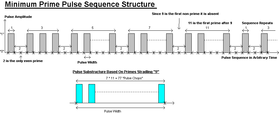
Now I would probably see some merit in adding "sub pulses" inside each pulse. This would not interfere with observing the sequence but would provide further evidence of intelligent design.
Since "9" is non prime and was avoided, it might seem clever to add sub chops inside with a quantity equal to the product of the primes either side of "9". This would suggest 7 · 11 = 77 "sub chops" inside each pulse.
Further, if the receiving bandwidth was insufficient to resolve these sub-chops the basic prime sequence would still remain. The sub-chops would just provide further evidence for intelligent design if they could be resolved.
I propose this structure as being a minimum prime pulse sequence with adequate structure to represent clear intelligent design. Of course, any other sequence could equally be searched for in parallel with this one and longer sequences may have advantages - this one is the shortest with a differentiation between prime, non prime, odd and even and even shows multiplication!
It is now necessary to determine the maximum optical receiver demodulation bandwidth based on a few simple considerations. This may be adaptive so we need an estimate for both an upper and a lower bandwidth bound.
The first consideration is that ultra high data rates are certainly not required given that it would take centuries for signals to reach us anyway. Further, high receiver bandwidths will impede our ability to detect presumably weak signals. Any transmissions therefore would assume that the remote receiving civilization may capture information sent over decades or even centuries.
However the data transfer rate has a lower bound. If the remote transmitting site assumes that the receiving civilization is on a rotating planet, then it has a finite time before this planet turns its "dark side" to the transmitting source.
Let us us our planet as an example. Our facing side is available for about 12 hours for signals reaching the equator. The message therefore has a maximum of 12 hours to complete its transmission to us. (it may repeat over many days of course but fragmented recovery of a message is unattractive)
Of this 12 hour period, the "quality" of reception will deteriorate at the time edges. It may be better to assume a percentage of "adequate sidereal availability" for our assumptions. For now let's assume 50%, i.e. we have 6 hours to fully capture a message.
During this period of adequate availability the proposed minimum prime data sequence has the following complement of pulses
Prime Number Data "1" Values 1 + 3 + 5 + 7 + 11 = 27 data "1" pulses
Prime Number Data "0" Values 0 + 2 + 4 + 6 + 10 = 22 data "0" pulses
Inter-data pulse "gaps" 5 lots of 2 unit time periods = 10 "0" distinguishing separating gaps
Total unit time "slots" 27 + 22 + 10 = 59 total unit time slots
Now lets first assume that sub structure pulses are not required. We therefore have 6 hours to receive 59 time slots so each slot has 6.1 minutes to be decoded. The minimum receiver bandwidth would equal the reciprocal of each slot time period, i.e. 2.73 Milli-Hertz.
However we would probably want to receive a message more than once for additional confirmation. Let's assume we want to do a "double take". The receiver bandwidth would need to double as each time slot is now divided by two, i.e. 5.46 Milli-Hertz.
This represents a lower limit but what if the transmitting civilization does not know our planet' rotating speed? We may need to consider some upper bounds as well. We have two main considerations for this
| What maximum rotation speeds would a remote transmitting civilization assume? | |
| Do we also want to cater for the possibility of addition pulse substructure including a sub-vision of time slots by the proposed factor of 77 |
We know we are not the fasted spinning planet in the universe. Would a factor of 10:1 be appropriate? If so the time slots would shrink by a factor of then so the receiver bandwidth would now become 54.6 Milli-Hertz.
Now let's add a scale factor to allow for the 77 sub slot divisions. To cater for these we need to increase the minimum receiver bandwidth by a factor of 77 times i.e. 4.206 Hertz.
Post capture digital signal processing can always be used to reduce the final demodulation bandwidth below this limit but the basic hardware only needs to support a minimum demodulation bandwidth of 4.206 Hz.
Now let's consider an upper demodulation bandwidth. Would a minimum prime number sequence be sent? After all, these low order primes are very closely spaced and far better credibility would be achieved from a much longer sequence. Further the transmitting civilization may want to switch between low and high order sequences to further prove their existence to the universe.
The closely spaced prime numbers are
1,2,3,5,7,11,13,17,19,23,29,31,37,41,43,47,49,51,53,57,59,61,67,71,73,79,81,83,87,89,91,97,101,103,107,111,113,117,119,123,127,129,131.....
In other words it takes a long sequence to get to where they are well spaced. Well spaced prime numbers are much harder to account for as perhaps generated from a natural source than a simple near-odd sequence of closely spaced primes.
This sequence shows 43 closely spaced primes compared to the minimum prime sequence I have proposed up to prime=11. The number of time slots must accommodate the maximum prime number, not the number of primes!. Prime=131 requires 131 as a maximum compared to 11. The additional bandwidth would be multiplied by this ratio of 131 / 11!
How high would a remote civilization assume its prime sequence go? Would it assume 1001 was an upper limit or would it want to sometimes go to a million?
Obviously a receiver will become noise limited as it's bandwidth increases but this can be adaptive to suit. After all, their would be plenty of time to send many different version of a sequence.
We are interested in setting a target specification for a suitable optical receiver that could accommodate the majority of possible sequences but maybe not all. A sufficient number of sequences would represent adequate proof to us. We need to decide what level of proof do we require.
Therefore I propose to set a target specification for a optical receiver that an amateur SETI enthusiast could be able to construct and use. We start with a minimum hardware imposed bandwidth (reducible further in software processing) of 4.206 Hz based on a minimum prime length sequence up to 11 with a 77 sub slot structure. Perhaps we would want to detect sequences up to 1001? The upper bandwidth would therefore be 383 Hz.
So far we have assume "minimum bandwidth" or equivalently "matched filter demodulation". This imposes serious constraints on the hardware. Minimum bandwidth or "matched filter" processing assumes an exact knowledge of the incoming symbol rate which we of course can not know. The remote transmitting civilization would of course know this. A better assumption is for a "gaussian filter" response. The target receiver bandwidth would need to increase in order to accommodate this, perhaps by a factor of two or three times. Further, designing an "exact" gaussian filter is perhaps un unwanted additional hardware overhead and a much simpler "Butterworth response" would be far more attractive (e.g. Sallen-Key Op-Amp based). This adds the need for some additional margin.
Let's take a stab and I will suggest 2 kHz as an upper bandwidth, hardware imposed limit and allow post capture software to have the option of reducing this down to any lower limit.
This upper bandwidth constraint also easily complies with the use of a computer's sound card (microphone input) bandwidth constraint which will be about 50 Hz to 16 kHz or so.
Computer sound cards are designed for receiving frequencies we typically can hear. It is technically unnecessary for these to accommodate frequencies outside this range. The do not allow DC input so low data rate signals would be corrupted.
The solution is to convert the optical SETI receiver output data stream up to a frequency range that is suitable for the soundcard. Although the best "center" placement would be in the middle of, say, 50 Hz to 16 kHz = 8.025 kHz, we must also realize that manufacturers of sound cards would obviously optimize these for the voice range of 300 Hz to 3000 Hz to save money.
However, if we selected the middle of this range, i.e. 1.650 kHz, then the upper bandwidth target of 2 kHz may not "fit well" depending on its transformed format (as a prelude it will be a frequency modulated offset).
We therefore need a compromise placement for the "transformed band center".
It seems sensible to me to set a middle placement between 1.650 kHz and 8.025 kHz for this, i.e. 4.8375 kHz for a linear average and 3.638 kHz for a geometric one. Again I would choose a round number between these two, so that is why I propose 4 kHz.
The easiest way to transfer a low frequency data stream to a higher centered one with high accuracy is to use frequency modulation (FM). The "carrier frequency" for this would be 4 kHz and it would deviate above and below this depending on the data value. This allows an analog format so that the computer can perform a frequency offset demodulation algorithm and reconstruct the data. This format allows post filtering.
The frequency deviation cannot exceed certain bounds. It should be reasonably high to provide a good signal to noise ratio but not so high to exceed the sound card's limits. This is a thumb guess at this stage, so I will just assume the use of an adjustable deviation limit from 0 Hz to 3 kHz.
However we have additional considerations. Post capture signal processing is a bit specialized and the amateur SETI enthusiast may not be comfortable with this. An additional option would be to "digitize" the captured optical signal in the optical receiver and send a 0-1 binary sequence to the computer's USB ports or RS232 etc. Several pre filtered options could be provided given to suit multiple digital inputs.
Many computers seem to favor multiple USB ports (my notebook has 3) so having 3 Bandwidth options would be suitable for it.
Consequently I will specify 3 bandwidth options for now, but the amateur SETI enthusiast can always extend on these!
The three bandwidth options will be 2 kHz, 200 Hz and 20 Hz, each converted to a binary 0-1 output.
(I may add a design for an analog interface at a later date)
The target optical sensitivity depends on several factors
| The optical sensitivity of the photo-detector in Amps per Optical Watt | |
| The additional noise introduced by post detector amplification | |
| The amount of "aperture area improvement" provided by the use of a collimating lens or reflector |
We have a number of possible options for an optical detector
| Light Dependant Resistor (LDR) | |
| Photo Diode | |
| Photo Transistor | |
| Photo Sensor Integrated Circuit |
I would immediately dismiss the LDR as a candidate. These devices are very non linear, relatively slow and are not intended for low optical noise operation.
The Photo Diode option, in comparison has extremely linear optical power to output current conversion and are often characterized with an optical noise power parameter. They can also be extremely fast (up to several GHz), although this is unnecessary in the SETI application.
The photo transistor combines a photo diode function with (usually) an unbiased NPN transistor in one package. These are intended for low performance on/off detection where the NPN amplification is used to overcome a relatively small light capture area. They do not have a noise parameter specification but it would be poor. They also lack linearity and are relatively slow. (See below)
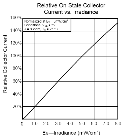
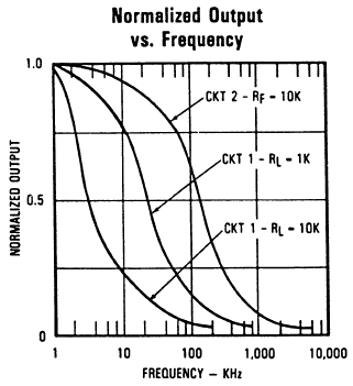
The photo sensor IC is a variant on the photo transistor whereby the NPN is replaced with an OpAmp in one package. They are also extremely linear but tend to have an upper bandwidth around 50 kHz (I will show later why this would be a problem). They are characterized for output noise voltage but not optical noise power - which is the critical parameter here.
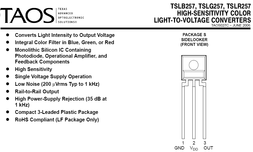
Consequently these devices are not suitable, although they often allow operation at lower wavelengths (e.g. towards the blue end of the spectrum)
The best candidate device is a photo diode with a large optical aperture area. Here is a suitable example device.
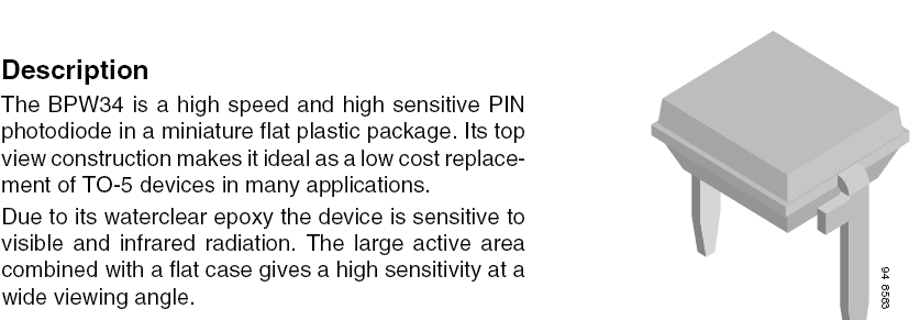
This one is actually a PIN junction type. These offer the highest possible switching speed and also have a wide optical bandwidth.
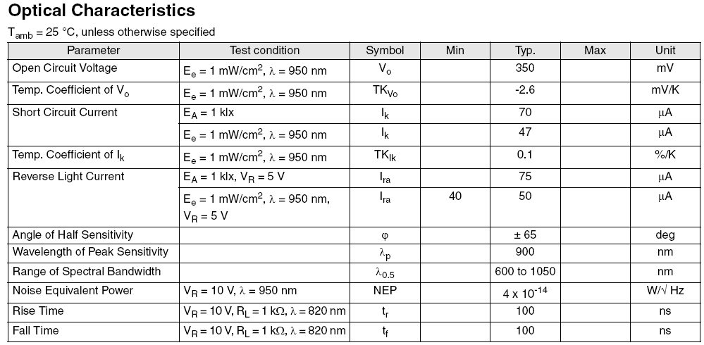
Note that the Noise Equivalent (optical) Power, NEP, is specified at 4 · 10-14 W/Hz0.5 corresponding to an optical input noise power of Popt = -104 dBm1Hz .
Note: PdBm = 30 + 10 · Loge { Pwatts }
If we recall the previous example using a small laser, the anticipated optical power available in a reception area of Ar = 9.4 mm2 was -130 dBm. This diode has a similar reception area of Ar = 7.5 mm2 .

Clearly the optical noise dominates by 26 dB.
In order to "just break even" we need to increase the reception area by an equivalent ratio of 26 dB = 400 times. This suggests the use of a focusing lens or reflector with an area equal to 9.4 mm2 · 400 mm2 = 3,760 mm2 and that this arrangement focuses all incoming light on the the reception area of the photo diode. This suggests (if a magnifying lens is used) a diameter of 1.196 meters.
This is perhaps unrealistic, even if a two or three step focusing process is used. Remember that the critical parameter is incoming aperture area unlike telescope related parameters such as size magnification.
We may well conclude that a small laser fired 1 light year away would be undetectable! Possibly a corresponding amateur SETI enthusiast may be operating in that distant solar system (although none are that close of course) but we would need to expect something a bit more substantial in operation. Still, the low cost technology available today seems reasonably credible to capture much stronger and less divergent laser signal sources even much further distant than this.
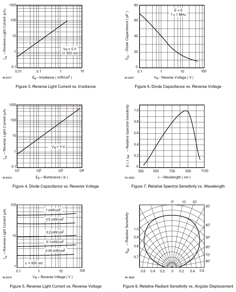
Finally, some additional graphs
The following graphs show extremely good linearity over a wide irradiance (optical power) range, low capacitance and wavelength reception from blue to red ends of the optical spectrum. Photo diodes of this type are good candidates and cost about $NZ 3.87 from Farnell.
A final note - unfortunately any incoming signals have to compete with star light and glare from street lights. Star light will cause "blips" as the earth rotates relative to their light. How can this be avoided?
The remote civilization, presumably would have considered this obstacle. They would consider static optical light to be a DC bias, and star "blips" to be a low frequency aberration. The solution is simple - use Amplitude Modulated Light.
Lets imagine their laser is modulated on/off at, say, 10 kHz. This represents a carrier frequency also of 10 kHz in the same way that an AM receiver has channels separated at different carrier frequencies. A "pulse on" represents an output of 10 kHz pulses, and a "pulse off" just represents turning the modulated laser source off.
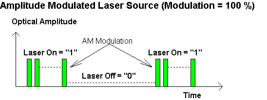
This method shifts the optical modulation away from DC so the receiver can ignore it, and low frequency aberrations caused by moving star light. A band pass filter will be placed after the optical detector and standard AM demodulation techniques will be applied.
| Parameter | Target Specification | Units | Comments |
| Supply Voltage | +9 | Volts | This will be internally regulated to +5 V etc |
| Supply Current | 100 | mA | Maximum expected value, presumable much lower |
| Minimum Optical Wavelength λmin | 450 | nm | Blue end of visible spectrum |
| Maximum Optical Wavelength λmax | 900 | nm | Red end of visible spectrum |
| Noise Equivalent Power | -104 | dBm1Hz | Requires low noise post detector amplifier |
| Aperture Area | 7.5 | mm2 | Based on suggested BPW34 photodiode without external focusing lens or reflector |
| Lowest Optical Carrier Frequency | 4000 | Hz | Has to exceed modulation bandwidth limit |
| Highest Optical Carrier Frequency | 100,000 | Hz | Best guess - little reason seems to exist to have high carriers |
| Post Detector Demodulation Bandwidth | 2,000 | Hz | Highest Low Pass Filter Option at -3 dB |
| 200 | Hz | Middle Low Pass Filter Option at -3 dB | |
| 20 | Hz | Lowest Low Pass Filet Option at -3 dB | |
| Analog Output Option | 0 to 4.0 | Volts | For external conversion to FM, suitable for a PC sound card |
| Digital Output Options | 0 to 5 | Volts | Standard TTL or CMOS voltage compatible outputs or USB if preferred |
The following system diagram contains all the signal processing componets that we have previously discussed in this web chapter.
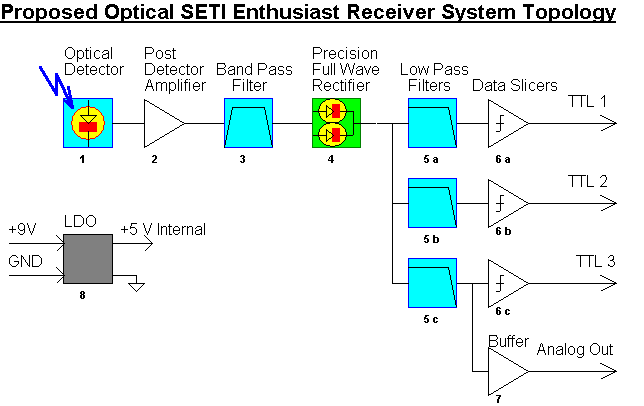
| ID | Name | Primary Function |
| 1 | Optical Photodiode Detector | Converts incoming Optical power to a linear current output. Must have low optical noise (NEP) |
| 2 | Post Detector Amplifier | Converts detector output current to voltage with "trans-impedance" amplification. Noise contribution must be low |
| 3 | Band Pass Filter | Removes unwanted DC and low frequency energy and sets an upper optical carrier limit. Can be wide band |
| 4 | Precision Full Wave Rectifier | Op-Amp (or equivalent) AM detector. Produces "base-band" output with low distortion |
| 5 | 5 a - Lower Low pass Filter | Defines Maximum demodulation bandwidth = 20 Hz, Sallen Key Butterworth |
| 5 b - Middle Low Pass Filter | Defines Maximum demodulation bandwidth = 200 Hz, Sallen Key Butterworth | |
| 5 c - Upper Low Pass Filter | Defines Maximum demodulation bandwidth = 2,000 Hz, Sallen Key Butterworth | |
| 6 | 6 a - Lower Band Data Slicer | Converts analog input to digitized 0 - 1 output. Should adapt to minimum and maximum at switch mid-way |
| 6 b - Middle Band Data Slicer | Converts analog input to digitized 0 - 1 output. Should adapt to minimum and maximum at switch mid-way | |
| 6 c - Upper Band Data Slicer | Converts analog input to digitized 0 - 1 output. Should adapt to minimum and maximum at switch mid-way | |
| 7 | Analog Buffer | Provides a unity gain buffered analog output for external FM modulator - intended to allow a PC to provide digital filtering and FFT analysis |
| 8 | Low Drop Out Linear Regulator | Allows low tolerance 9 volt supply input to be used without injecting noise into the internal circuitry |
In this web chapter I have presented some of the issues that confront the search for intelligent life in outer space. The vast interstellar distances result in significant signal path loss, resulting in potentially unrecoverable weak captured signals, assuming they were sent. Further the finite (and constant) speed of light applies equally to radio waves, so any signals that may be received could easily have come from a distant civilization centuries in our past. Two way communication would therefore be unrealistic.
We developed a path loss model to predict the likely loss and concluded that accidental interception of remote signals would be unlikely. A distant civilization would need to make special provisions for us to intercept any message. This would involve vast amounts of transmit power combined with ultra high gain transmission antenna even for nearby solar systems. Equally we would need similar antenna and ultra sensitive receivers requiring ultra low demodulation bandwidths.
It appears therefore that government funded initiatives would be needed to produce the necessary reception infrastructure for such a venture. The technology and finance required would be beyond the means of an amateur SETI enthusiast.
In comparison we examined the case for "optical SETI". This appeared far more promising. Unlike radio transmission, laser sources are automatically narrow bin point beams and can target a remote reception site with far better precision. This allows a much higher percentage of the transmitted energy to be captured.
Indeed even a modest small laser would almost bridge the gap for a one light year hop and result in received optical energy that would almost be visible to the human eye.
Further the scope of available optical power sources currently in development here on earth range from a standard 3 kW output up to a planned 700,000,000,000,000 W i.e. 700 TW. Further the use of a wider transmitter aperture would allow much less optical divergence, further helping to pin-point the energy to an intended target.
Given that an optical signal was received we then discussed the requirement to distinguish between a real extra terrestrial source sent by an intelligent civilization and other artifacts that have have arisen from natural causes or being the accidental or intention by product of human activities here on earth. I proposed the use of a binary sequence of primary numbers would be extremely difficult as being a natural creation. Further, embedding a sub structure demonstrating the multiplication to two prime numbers would add additional weight of evidence to the case for intelligent signal creation.
The bandwidth and data rate constraints were then discussed. We concluded that a lower bandwidth would be around 2 Hz due to the finite time the face of the earth would be available to a possible optical source and 2,000 Hz as an upper limit to allow sub structure detection and longer prime number sequences.
I then proposed the use of an amplitude modulated sub carrier to remove static ambient light or low frequency variation caused by the passage of stars as the earth rotated.
Finally we discussed the selection of suitable optical detection devices and included that a photo diode detector would be the best option. A candidate device was proposed, readily available from Farnell at less than $NZ 4 and summary data was presented. The concept of Noise Equivalent (optical) Power was discussed, along with receive aperture size and the possibility of adding a focusing lens or reflecting dish to increase optical sensitivity.
Given the reasoning presented, a target specification was presented that would be within the means of an amateur SETI enthusiast to respond to with appropriate home made hardware.
A simple system diagram topology was then presented that would guide any subsequent circuit level design.
I hope this web chapter on SETI has been a fun and interesting and informative conjectural. I have certainly enjoyed writing it and thinking through the technical issues over the last few weeks. Someday I plan to build such hardware myself and leave it fixed, pointing into the inky sky with a permanently connected computer for continuous analysis and possible detection.
If I discover anything I'll let you all know!
Knowing my luck I'll probably get some pesky UFO flying in the way just at the worst possible moment!
![]()
Return To Conjecturals
or to Ian Scotts Technology Pages
© Ian R Scott 2007 - 2008