![]()
US scientist Joseph Henry (1797 - 1878) invented his "electro-magnet" consisting of many turns of wire coiled around various iron shapes. His familiar "horse shoe" magnet could be connected to a battery and used to pick up small magnetic objects and release them when the current flow was interrupted by an open switch. Joseph Henry used this principle to also operate a second switch that could interrupt an even larger current flow demonstrating the principle of a "relay". Samuel Morse, it is said, later swiped this invention to patent it as one of his own in the invention of the telegraph, also using electro-magnets. It appears that Joseph Henry did not contest this patent but went on make further discoveries in electro-magnetism based on concepts of self induction, mutual induction (e.g. as used in transformers) and the first electric motor.


Following such early discoveries many theoretical refinements were contributed by enthusiasts in electricity and magnetism. Ampere postulated
![]() ...(1)
...(1)
Although this closed form expression appears simple, its application to many physical structures paved the way for expressions that predicted inductance for a given geometry.
Michael Faraday then postulated a expression for "induced electromotive force or EMF" associated with a rate of change of magnetic flux Ø with time
![]() ...(2)
...(2)
In this formulation, a change in flux could be caused through the motion of an inductor through a magnetic field or from the variation of a magnetic field without motion. When combined with the concept of inductance L, a "back EMF" prediction could be made
![]() ...(3)
...(3)
From this we interpret the action of inductance is to resist any change in currents flowing through it. From a frequency domain perspective, this action is seen as a reactive impedance that is proportional to frequency
ZL = j · XL
XL = 2 · π · F · L ...(4)
The imaginary operator j ≡ √ (-1) is included to represent a 90 degree phase lag between inductive current and applied AC voltage.
Given that an applied current creates a magnetic flux, and that energy is return from any reduction in this flux, energy storage must occur. The actual amount of stored energy is
E = ½ · L · I 2 ...(5)
Various materials were found to modify the magnetic field for a given flux and therefore the associated inductance. These could have a small negative effect but useful materials were found to have significant "field amplification" properties. The "permeability of free space" or that permeability exhibited in a vacuum is identified with the Greek letter µ and is defined to have a value
µ0 ≡ 4 · π · 10-7 N A-2 ...(6)
The actual permeability µ depends on the relative permeability µr of material introduced into the complete magnetic field
µ ≡ µr · µ0 ...(7)
If the introduced material only partially intersects the magnetic field (i.e. some of the field remains in "free space", then an "effective relative permeability" can be defined. This effect is exploited in magnetically tuned inductors and also in transformer core "air gaps" intended to trade inductance for improved current handling capability before magnetic saturation occurs in the introduced substance.
The permeability of some common substances used in magnetic circuits can be seen in the following table
| Material | Permeability µ · 10-6
N A-2 |
Relative Permeability
µr |
Comment |
| Vacuum | 1.256671.. (i.e. µ0 ) | 1 | µ0 ≡ 4 · π · 10-7 N A-2 |
| Nickel | 125 | 99.5 | |
| Steel | 875 | 696 | |
| "Soft" Ferrite | 2,500 ~ 5,000 | 1,989 ~ 3,979 | Ferrite is electrically insulated internally and externally and has excellent high frequency properties up to 300 MHz depending on "grade". |
| Transformer Iron | 5,000 | 3,979 | Usually implemented as flat insulated sheets to reduce "eddy current" losses |
| Permalloy | 10,000 | 7,958 | |
| Mu-Metal | 25,000 | 19,894 | Used for magnetic shielding enclosures |
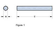
It may seem odd to predict the inductance of a lone piece of wire without a return current path but I dug up a formula for it anyway. The inductance is approximately proportional to length (with an additional logarithmic term) and inversely proportion to the logarithm of the wire's diameter
 ...(8)
This formula allows for the possibility of magnetic wire, e.g. iron, with a strong contribution from its relative permeability µr . Most high permeability substances are relatively poor conductors and little practical use exists for this. The preferred conductor is copper or copper with silver coating. Both of these metals are non magnetic, i.e. µr = 1.
 ...(9)
However it became apparent that the formula derived for DC conditions tended to deviate when AC operation was considered. This observation was attributed to "skin effect", a phenomenon that seemed to concentrate the flow of electrons near the surface of a conductor as the AC frequency increased. A slight corresponding modification was added to the inductance prediction formula, which tends to this result as the operating frequency tends to infinity.
 ...(10)
The analysis of two parallel inductors is probably far more realistic than the previous example and would directly apply to "300 Ohm ribbon cable" used an antenna connection to a remote TV set.
 ...(11)
This time we observe the inductance to be almost proportional to length but with a small additive correction term x/d depending on the separation between each wire. The actual inductance increases with this separation presumably due to a reduction in mutual coupling between each wire. Since the currents flow in opposite direction, this coupling will tend to cancel a portion of the total flux thereby reducing overall inductance as the wire spacing is reduced..
The inductance of a square wire loop can be considered to a reasonable approximation as a combination of a horizontal pair of wires connected in series with a vertical pair of wires.
 ...(12)
We see that equation (12) predicts twice the inductance of equation (11) with a small correction. Although the magnetic fields are orthogonal between horizontal and vertical wire pairing, some "oblique angle" interaction does occur so that equation (12) is not strictly accurate. A more complex equation, accounting for this interaction should be used if maximum accuracy is required e.g. an improved formula can be found from Wikipedia http://en.wikipedia.org/wiki/Inductance
Square wire loop inductors have been used for Medium and Shortwave "magnetic field" antenna and can have multiple turns for increased inductance suitable for lower frequency operation. Single loop magnetic antenna's are also used as a space efficient antenna in small Paging Receivers. These applications trade small size against optimum reception efficiency. The Paging receiver antenna is usually implemented as a PCB track as opposed to a wire loop for convenience, leading to a small error in the overall inductance estimate.
As a note, a rectangular loop can be used, but a square loop will provide the maximum inductance for a given length of wire.
A circular loop can also be used as an antenna or as an inductor per se
 ...(13)
A circular loop forms the basis of a solenoid coil consisting of multiple circular loops connected in series but with mutual magnetic coupling
 ...(14)
Equation (14) is reasonably accurate for long solenoids (compared to its to radius) but may require a small correction if a physically short solenoid is used as seen below in equation (15)
 ...(15)
We see that the denominator correction tends to 1 as the length tends to infinity, in which case equation (14) is obtained.
The following drawing shows the magnetic field associated with a solenoid. From this we see why a correction term is needed for a physically short solenoid. A long solenoid has internal magnetic flux lines that are parallel for the length of the solenoid whereas a short solenoid will not. This represents a loss of flux internal to the winding, causing a corresponding loss of inductance
The "ultimate solenoid" is obtained when the turns are arranged in a torus. This arrangement ensures that all magnetic lines of flux remain parallel to the windings and that none is lost from "end effects" as in the case of a simple solenoid
 ...(16)
It may be thought that the inductance of a geometric arrangement of conductors would automatically be multiplied by the relative permeability of a magnetic material added to it i.e.
![]() ...(17)
...(17)
However this assumes that all the lines of magnetic flux pass through the material and this may not be the case, A Toroidal inductor will closely approximate the prediction of equation (17) as most if not all the magnetic flux is retained inside its windings. A open ended solenoid on the other hand is not so lucky as some magnetic flux escapes from both ends. In this case an "effective relative permeability" µr, effective may be more appropriate
![]() ...(18)
...(18)
This effect is used to advantage in manually adjustable inductors. The magnetic material (e.g. ferrite) is adjusted to sit inside the coil or moved out to one end, reducing the effective permeability and therefore the corresponding inductance
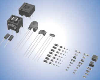
Although inductors have a wide range of forms and applications I will just illustrate some typical varieties that may be used by professional and amateur electronics enthusiasts. These can be identified under the following six categories
| Power Inductors Used In Switch-mode Power Supplies | |
| Power inductors for fluorescent lamp ballasts | |
| Small Signal RF Inductors | |
| Printed Circuit Board Inductors | |
| Ferrite Bead Decoupling Inductors | |
| Tunable Inductors |
Switch-mode power supplies have progressed immensely over the last half century, beginning with the mechanically oscillating "inverter vibrator component" used to switch a DC power supply on and off prior to voltage step-up by a transformer suitable for high voltage generation suitable for electronic valve radios and transmitters. The clumsy and somewhat unreliable relay contact based switchers were replaced with solid stage transistors that, at the time, could achieve high current handling capability but were far too "slow" for radio frequency use.
Transformers are comprised of two or more magnetically coupled inductors (and I may add another web chapter on these later) and are appropriate when electrical separation (isolation) is required between input and output circuits of a switch-mode power supply. However the "simple" inductor based power supply solves a vast majority of circuit problems and are used extensively in small electronic portable equipment were various internal device technologies have conflicting voltage supply needs.
Component manufacturers such as National Semiconductor, Linear Technology, Maxim-ic, Analog Devices, Texas Instruments etc provide excellent, easy to implement switch-mode, inductor based voltage converters based on the following generic topologies (examples from National Semiconductor)
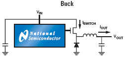
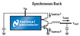
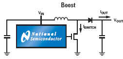
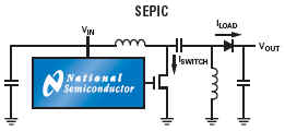
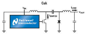
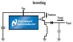
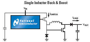
These IC solutions place critical performance requirements on the inductors used for energy transfer from input to output circuits. These need to operate at frequencies ranging from F = 20 kHz up to F = 3 MHz based on current semiconductor technology limitations, and exhibit minimal power loss (as heat) within a small package size as demanded by modern trends towards miniaturized electronic products. An example "simple switcher" available from National Technology shows a typical medium power voltage converter required for powering a CPU core operating at Vs = 1.8 volts and drawing currents from Is = 80 mA to Is = 600 mA.

Since battery life is of paramount importance, any efficiency compromise cause by inductor losses is viewed with extreme contempt by IC component designers that send significant time and resources to achieve the best possible semiconductor limited voltage conversion efficiency.
The use of ever increasing switching frequencies allows the inductor volume to shrink correspondingly but places additional demands on the frequency dependent losses of magnetic materials (e.g. ferrite compounds). Significant advances have occurred in this area of composite material technology. On the other end of the technology scale we have inductors that operate at lower frequencies dictated by mains (line) AC power frequencies. These inductors are often used as "ballast" series connected current limiting components as required by fluorescent light bulbs operating at F = 50 Hz (NZ, Europe) to F = 60 Hz (USA).

Once again we see the pervasive creep-age of electronic solutions to older, historically based methods for current limiting ballast inductors. Previous ballast inductors operating at the direct mains ac frequency need to have large inductance values in order to provide an adequate series reactance. For example, a 60 watt fluorescent lamp may have an end to end terminal voltage as low as 60 Volts suggesting an AC current of 1 Amp RMS. When operated from a mains supply voltage of 230 Vac the inductor would need to "drop" an AC voltage predicted from Vballast = √ ( 2302 - 602 ) = 220 Vac implying an inductive reactance equal to Xballast = 222 Ohms (vector subtraction). If the AC mains frequency is F = 50 Hz, the ballast inductor would need to be L = 0.71 Henries.
Inductors of this size need to be large and costly due to materials used and time required for overall construction. An "electronic ballast" solution is now the favored approach in almost all new fluorescent lamp applications - most prevalently used in Compact Fluorescent Lamps (CFLs). This approach uses a relatively simple self oscillating switch-mode converter operating typically at F = 50 kHz as opposed to the old fashioned approach that operates directly at the much lower mains frequency of F = 50 Hz. This much higher operating frequency allows the use of a ballast inductor that has an inductance value in the region of one thousand times lower e.g. Lballast = 0.7 mH !
This massive reduction in size and cost more than compensates for the cost of any electronic components. Once again we see the farewell wave to old, traditional approaches to power management.
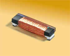
Inductors are also required for radio frequency applications. These inductors are available from from low frequencies similar to those used in switch mode power supplies (e.g. F = 455 kHz used as an IF frequency in many AM radios) up to frequencies as high as F = 5 GHz used for local area wireless network products.
These inductors are usually based on a solenoid coil construction with a ferrite core for frequencies up to about 300 MHz and ceramic for higher frequencies. Surface Mount Devices tend to dominate. These small signal inductors are generally suitable for RF power levels below 1 watt and have inductor values that range from several milli-Henries (mH) down to a few nano-Henries (nH).
In some cases, low value inductors are formed from copper traces on the PCB substrate so that an additional inductor is not required. This implementation is based on a transmission line approximation to an inductor, valid providing that the characteristic impedance is high relative to circuit impedances and that the electrical length is much less than one quarter wavelength at the intended operating frequency
L ≈ Z0 · LE / Vf
where Vf = c / √ εr
Although ferrite materials have frequency dependent electrical loss depending on their specific composition or "grade" this property can be used to advantage in power supply decoupling circuits. Although decoupling capacitors are available with extremely good decoupling properties (low impedance) they may not be adequate for some applications. Further, many electronic devices require local power supply decoupling and PCB tracks interconnecting these decoupling capacitors can cause an unintentional resonant circuit (the same problems can occur for parallel connected capacitors).

These accidental resonance's can result in unexpected circuit behavior anomalies and be fairly difficult to track down especially in large PCB layouts with multiple devices operating over a wide range of potential frequencies. This possibility becomes progressively probably as technology advances in capacitors result in ever decreasing loss and associated increases in component "Q". A precautionary approach is to add a low Q series inductor to each prospectively interacting PCB track so that these accidental resonance's are "damped out".
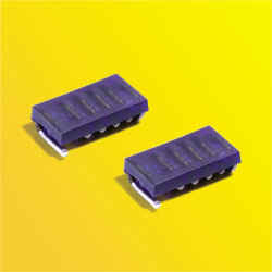
Ferrite beads have an extremely simple construction consisting of a wire surrounded by ferrite material and are typically offered in standard SMD package sizes e.g. 0402, 0603, 0804 etc. They are available in a wide range of inductor values and DC current handling capability (limited by ferrite magnetic saturation as opposed to over heating) and have specified RF loss characteristics over a wide range of potential frequencies ranging from a few hundred kHz to hundreds of MHz.
Finally, tunable inductors are available for manual adjustment in some RF circuit design approaches. Once again, human intervention is contrary to philosophies associated with Design For Manufacture or DFM. However, many tunable inductors are available (Coilcraft, Toko, etc) and use a solenoid construction with a physically adjusted ferrite (or aluminium) core position internal / external to the winding.
Here are some medium power inductors from Coilcraft intended for medium power switching regulators. A very attractive feature is small size combined with appropriate inductance values and current handling capability.
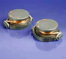
Higher power versions suitable for currents up to 3 Amps are also available. These are commonly used with National Semiconductor's "simple switcher" IC's such as the LM2676
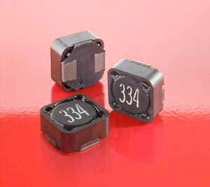
Although these inductors are magnetically shielded, the Toroidal inductor family offers even lower unwanted magnetic radiation (reduced EMI)
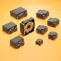
It seems that Coilcraft continues its innovations in cost effective inductor implementation. Here is an example showing the use of stacked PCB based coil windings used to construct a high power switch mode inductor with highly streamlined manufacturing process steps
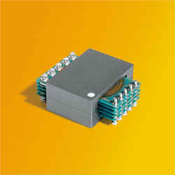
According to their published literature, many transformer configurations are readily provided with this approach
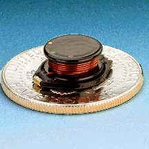
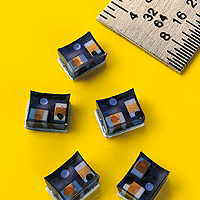
The development of advanced inductors targeting switch mode power supplies is certainly enjoying a period of continuing growth. To finish off this web chapter, here are some ultra small switch-mode inductors rated to 2.6 Amps in a footprint size of 1.8 by 2.0 mm and only 1.0 mm high
These inductors are often provided in SMD format and are suitable for medium power RF applications less than a few watts with DC currents ranging from tens of mA to several Amps
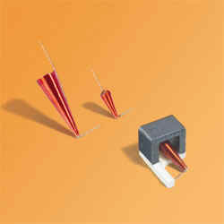
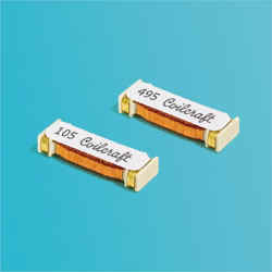
Typical RF "Q" values range from Q = 20 to Q > 200 depending on frequency, size and construction materials. The following "mini spring" inductor example (Coilcraft) has a published value of Q=250 at F=1 GHz and can support a DC operating current as high as 4 Amps (presumably these might be used in the output matching networks and low pass harmonic rejection filters associated with high power VHF and UHF RF amplifiers operating up to 50 Watts output).
Extremely wide band "conical inductors" are also available. The use of this variable diameter format helps reduce accidental internal resonances and allowing a flat bandwidth up to frequencies as high as F = 40 GHz!
The most common format is a single layer solenoid but some stacked plate ceramic constructions are also available
 (
KOA Speer Electronics)
(
KOA Speer Electronics)
As if to continue into even further burgeoning territory, integrated RF filter solutions consisting of multiple inductors and capacitors are also now on offer (Coilcraft example)
So it seems that a humble piece of scrunched up wire is anything but ordinary in today's Component Universe!
Inductive loop antenna's are often used in small VHF and UHF paging receivers were small size and completely enclosed operation is of paramount importance. These are usually printed as a single tuned (resonant) loop or PCB track that is electrically small compared to a wavelength. Magnetic material is sometimes included to improve efficiency or reduce size for a given efficiency.
I will include an analysis of these "home made" resonant loop antenna's in this web chapter Antenna
Ferrite rod "open magnetic" antenna's are commonly used in low cost portable AM radios. These use a simple ferrite rod with medium permeability, low loss composition surrounded by a wire coil solenoid winding (usually single layer with about 50 turns). An example ferrite rod from Fair-rite is shown below
Other ferrite antenna applications involve RFID (Radio Frequency Identification) products operating up to F = 150 kHz. These are intended for short range operation up to several meters distant
Once again the construction is based on a solenoid winding with an internal "open magnetic" core
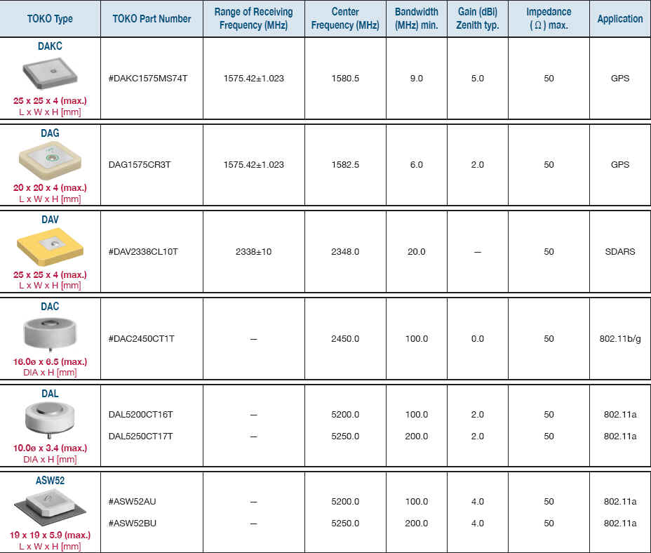
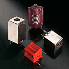
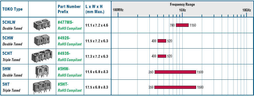
Other antenna used for microwave operation (e.g. 2.45 GHz) are not really "inductors" but use magnetic and electrostatic fields for their operation and so will be mentioned here. Here are some "dielectric antennas" available from TOKO
The use of ferrite bead EMI suppression products has skyrocketed over the last few decades, fuelled by continuously developing ferrite material compositions and the commercial pressures on size reduction and streamlined manufacturing processes leading to cost effective component solutions. Leaded and SMD offerings are available with manufacturers such as Murata etc providing extensive varieties.
Ferrite beads are optimized for a wide range of frequencies and provide high AC impedance combined with extremely low Q (i.e. almost completely resistive) and very low DC resistance. Some ferrite beads produce impedance maxima below 10 MHz whilst others exhibit their greatest effectiveness well above 1 GHz.
In pursuit of ever present demands for space reduction, ferrite EMI suppression inductors are often integrated with additional decoupling capacitors to form low pass filter topologies


The effectiveness of these composite EMI suppression filters is often characterized as attenuation measured in a 50 Ohm reference circuit
Continuing this philosophy, various manufacturers incorporate multiple EMI suppression circuits in a single component. This example from Murata shows 4 independent EMI filter circuits
Ferrite beads have a DC current rating that is dictated by magnetic saturation in the surrounding ferrite material rather than arising from any internal heating. Ferrite beads optimized for lower frequencies require high permeability ferrite and these ferrite grades tend to saturate at lower currents (e.g. 100 mA) compared to lower permeability, high frequency versions of comparable size. Given that the construction is usually based on a short straight length of wire encased in insulating ferrite material, the DC resistance is primarily determined by end contact effects and can be in the order of 10 mΩ allowing current ratings up to 6 Amps or higher.
Some example "hexagonal ferrite core" 10 mm shielded inductors available from Coilcraft are shown below. These can offer reasonable Q values up to about Q = 100 and be useful at frequencies up to 300 MHz.
Since ferrite material, based on current compositions, shows increasing loss with frequency, operation above 300 MHz tends to be ill-favored in component offerings, unless low Q operation is specifically called for (e.g. as in ferrite beads for EMI suppression). In some cases, an aluminium core can be substituted. Although aluminium is non magnetic, such a core acts as a "shorted turn" inside the winding and reduces the effective inductance as it is introduced into the coil's internal magnetic flux.
Other high frequency tunable options include "Helical Filters". These consist of coupled inductors with a tunable end capacitance formed by a ground connected variable cap. This does not vary the inductor value but is intended to shift the filter's resonant frequency. Some examples from TOKO include
In this web chapter we have witnessed a wide variety of inductors with differing geometries, materials and applications. The Component Universe of inductors is not starved of members. Inductance formula have been presented for straight wires, parallel wires, square wire loops, circular loops, solenoids and toroids. Further the introduction of magnetically active materials such as iron and ferrite composite materials has been described.
Inductors are used for high power switch-mode voltage conversion systems and this technology directly applies to portable electronic devices and even encroaches now the traditional bulky fluorescent light "ballast inductor" applications. Inductors are also available for medium power RF applications up to many GHz as high Q components and also as broad band "chokes" that remain "resonant free" up to frequencies that exceed 40 GHz!
Other applications resemble "AC resistors" with low DC resistance as exhibited by ferrite bead inductors. These components are specifically intended to avoid accidental resonance's in power supply decoupling networks.
The ever swelling pressures for miniaturization result in combined inductor and capacitor filter networks intended to reduce overall product size and component count.
Some inductors are used for magnetic antenna use, either as receiving antennae for AM portable radios or low frequency RFID tags
Inductors can be fixed in value or variable. Inductors can be purchased as a component or implemented for free by using existing PCB real estate for printed inductors with low inductance values required for VHF frequency operation and higher.
It appears that the future for inductors is alive and well! I hope my web chapter has illustrated the wide range, availability and direction of progress that this component family enjoys.
![]()
Return to: A Component Universe
or: Ian Scotts Technology Pages
© Ian R Scott 2007 - 2008